


Page 86 - index
P. 86
Technical description of GT602 R65 measurements


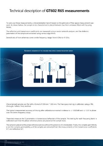
        To carry out these measurements, a characterization bench based on the principle of free-space measurement was
        used. As shown below, the sample to be characterized is placed between two horn antennas fitted with focusing
        lenses.                                                                                                                                                           Thickness :
                                                                                                                                   Transmission coefficient module S 11  (dB)             Reflection coefficient modulus S 21  (dB)

        The reflection and transmission coefficients are measured using a vector network analyzer, and the dielectric
        parameters of the sample are extracted using various algorithms.

        Several sets of horn antennas cover a wide frequency range, from 6 GHz to 42 GHz.


                             schematic diagram of the focused free space characterization bench                                                                                                                                 Thickness :


                                               Focal
                                               disTance   lens                                                                                       Frequency (GHz)                                         Frequency (GHz)

                                     TransmiTTing                        receiving
                                      anTenna                             anTenna

                                                            maTerial
                                                           under TesT
                                    To                                          To                                                   Permittivity
                                  analyzer                                    analyzer                                                                                                       Permeability
                                                                                                                                                                         Thickness :
                                                                                                                                                                                                                                 Thickness :


                                                                                                                                  Permittivity                                           Permeability


        Characterized samples are flat with a format of 300 mm * 300 mm. The free-space test rig is calibrated using a TRL
        (through / reflect / line) method.

        The typical measurement accuracy of this rig after calibration at normal incidence is +/- 0.025dB and +/- 0.5° in phase                       Frequency (GHz)                                          Frequency (GHz)
        over the entire frequency range.


        These test measure the S parameters in transmission/reflection of the sample. The test rig for each frequency band is
        calibrated such that the phase reference planes are placed at the sample faces.

        The sample is placed at the phase reference planes without the presence of a metal plate. Finally, the complex permittivity
        ε and the complex permeability µ of the samples are extracted from the measurements of the transmission coefficients                                      Additional data are available on our website
        S11 and reflection S21.


        86
        375 Avenue Morane Saulnier 78530 - Buc, France                                                                                                                                                                 www.getelec.com  87
        Tel : +331 39 20 42 42 | info@getelec.com

